In recent years, tracking systems have established themselves as a good means of increasing the efficiency of larger greenfield installations. With good reason: By adapting to the angle of incidence, tracking systems generate higher yields than fixed arrays. The economic benefit usually by far outweighs the more expensive support structures. Uniaxial systems have prevailed in day-to-day practice. Compared to biaxial systems, they are more robustly engineered, require less surface area and are thus more cost-effective.
Strong torsional forces
The dominating uniaxial tracking systems on the market are generally all constructed similarly or even identically. Driving the individual rows is done via a central shaft that is responsible for swivelling the panel array. Although this design is quite simple, it brings with it a serious technical challenge: Throughout the length of the central shaft there are considerable torsional forces at work due to wind and the inherent weight of the array, which need to be controlled.
With the length of rows ever increasing up to 120 metres, this is no easy matter. Furthermore, because almost all of the common systems are only able to absorb these torsional forces in only one place for every row: at the central drive unit. The residual elasticity of the central shaft can result in strong torsion over the length of the entire row. That makes such constructions susceptible to wind-induced vibrations along their axis of rotation.
Build-up of oscillations due to runaway effect
Even at slow wind speeds, these vibrations can build up dangerously to what is known as a runaway effect, a self-amplifying motion of the entire system (resonance). As soon as a torsion-flexible system – in this case, the central shaft – is twisted as a result of an outside force, the overall system is preloaded like a spring. The result: An opposing force gradually builds up within the mechanical system that matches the outside force, and the build-up of force and opposing force causes the system to oscillate.
In combination with the inertia in the system, certain frequencies of oscillation can cause it to swing too far, meaning that it will then swing back beyond its starting point: The oscillations will get out of hand and become uncontrollable.
Mutual effect of multiple rows as a result of shedding vortices
When it comes to larger PV projects, it is crucial to not only consider the aerodynamics of the individual trackers, but also what influence the rows of trackers have on each other. Vortices shed by one row of trackers will put additional pressure on the neighbouring one.
Practical cases of damage
The forces that can result from wind-induced oscillations can be so dominant that even the most massive structures fail. The best-known example must be the collapse of the Tacoma Narrows Bridge. This 850 metre suspension bridge in the US state of Washington spectacularly collapsed in November 1940 as a result of wind-induced self-amplifying oscillations.
Research has shown that flexible structures like PV trackers are particularly at risk of aero-elastic phenomena, such as runaway effects. Several cases of damage to uniaxial tracking systems in recent times have demonstrated this, some spectacularly so, and pointed out of the problem’s importance during project planning. Incidentally, these cases of damage due to resonance tended to happen at wind speeds considerably below the maximum that the installations were designed to withstand.
Safe in theory: hydraulic dampers
Hydraulic dampers are currently a common measure to avoid such oscillations. That requires the inclusion of a number of dampers per row that are specifically designed to counteract that pattern of resonances. Generally speaking, hydraulic dampers are useful for reducing the risk of a runaway effect. However, the application and dimensioning of these is anything but trivial.
Added to this, there are a number of practical disadvantages that have practical applications: Hydraulic dampers are subject to wear and tear and have a limited service life. If they fail or degrade in performance, for instance because they were not replaced in time, that can have severe consequences. The frequency of damage cases shows that improper dimensioning, faulty installation, a lack of maintenance or mechanical failure can result in the destruction of entire installations – and that even at moderate wind speeds.
In other words: The physical phenomena have been thoroughly studied and are well-understood. In principle, with the application of hydraulic dampers, they can even be controlled. In practice, however, this approach still comes with the risk of a variety of potentially catastrophic outcomes. And then there is the argument that using dampers is actually just a stop-gap measure. It does not address the problem directly. In order to achieve that, the system has to be fundamentally redesigned.
The key: evenly distributing loads
And that requires looking closely at the core of the problem, which is that conventional uniaxial trackers have only one point per row where the load is transferred. For fixed systems, that is not the case. Here, the surface of the panels is held up by each of the posts, which in turn directly transfer the load down into the ground. With the loads being thus distributed and transferred into the foundation gives the overall system a much lower residual elasticity and prevents the formation of wave-like oscillations across the entire length of the solar array.
So the key question is: How can the principle of an even distribution of loads into the posts of the substructure be applied to a tracking system? What is required is to prevent the panel surface from twisting at every post, without compromising the desired tracking-functionality of the system overall. This situation is aggravated by the fact that the direct transfer of torsion forces has to be freely adaptable to the array’s current angle of inclination.
Self-arresting gear arch
This is where using a gear arch in combination with a self-arresting functionality at every post is a good alternative. The gear arch unites the support and adjustment functions in one component. It holds up the panel array – as if it were a fixed mounting system – but at the same time allows it to track. And there is one other benefit: The gear arch transfers the loads from the panel array to the drive shaft further down the post. That means that the torsion and drive forces at the intersection with the post are already significantly reduced.
Nevertheless, even such a design also requires a continuous drive shaft as long as the entire row. There are, however, two key differences to the more common central drive shafts: First, because of the reduced gear ratio, the forces acting on it are much less; second, because of the self-arresting feature, it only has to transfer the driving forces along its entire length. The supporting forces are transferred into the ground locally through each of the posts.
As stable as a fixed mounting system
This is made possible by what is known as a Geneva drive. And exactly such a drive is at the heart of Schletter’s newly developed tracking system. With such a latching mechanism, the gear arch is locked in position by a centrally positioned cam during the rest phase. This achieves mechanical self-locking when the tracker is at rest. All occurring loads are transferred directly into the posts and thus into the foundation. No loads are applied to the drive shaft, the engine or the gearing.
If the tracker is to be moved, a motor positioned centrally in the row rotates the drive shaft. This unlocks the holding cam, while another external cam engages with a recess in the gear arch and moves it in the desired direction. As soon as the tracker reaches the desired position, the self-locking mechanism engages again. The Geneva drive locks back into the rest position and the supporting forces are transferred locally through the posts.
Oscillation impossible
This design has a massive advantage: The mechanical self-arresting feature gives the system the stability of a genuinely fixed mounting system. It does not require additional components such as dampers or other stopgap measures to reduce the oscillations. This makes the tracker designed based on this principle by Schletter invulnerable to aero-elastic phenomena, particularly the dangerous runaway effect. Catastrophic oscillations, as could occur in systems with a central shaft, are now absolutely impossible.
First pilot project under construction
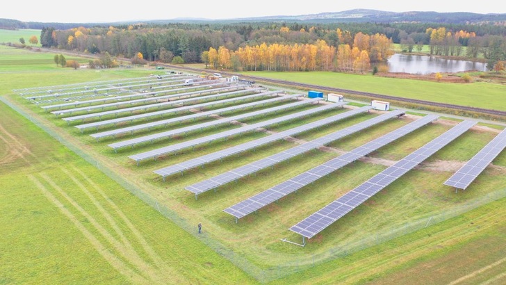
Schletter presented their newly developed tracker at this year’s Intersolar Europe as well as at a variety of other international trade fairs, such as the SPI in Anaheim or the All Energy Australia. In Freihung in Bavaria, a first pilot project by the Nuremberg-based Solarpower Project Invest is being realised. It is scheduled to be completed by December of 2018.
The authors are Gabriel Dechant, Stefan Spork and Dr Cedrik Zapfe of the Schletter Group.
Keep up with innovation in PV! Watch our PV Guided Tours at The Smarter E Europe in Munich:
https://www.pveurope.eu/Videos/pv-Guided-Tours-videos-2018
Stay informed, get our newsletter twice a week.
Register here: https://www.pveurope.eu/Newsletter
Read more about solar modules.
Read more about solar mounting systems.
Read more about solar energy storage.


